PHP 7.4.30, Port 443
Session Debug is OFF
Session ID NNmS1
Azure Web App Test Site
Menu

Wiring Diagrams

  Back to Reference Information
Some wiring diagrams

Wiring diagram for standard 7x12 (C2) mini lathe with red and yellow emergency stop switch. FC250J/110V control board.

Wiring diagram for mini lathe with red and yellow emergency stop switch and upgrade 350-watt FC350BJ/110V control board. 

Wiring diagram for standard HF 7x10 mini lathe with illuminated rocker power switch. Fl250/110V control board.

Wiring diagram for HF 7x10 mini lathe with illuminated rocker power switch and updated 250-watt controller. Jumpers added to defeat interlock circuit. FC250J/110V control board.

Wiring diagram for HF 7x10 mini lathe with illuminated rocker power switch and upgrade 350-watt controller. Jumpers added to defeat interlock circuit. FC350BJ/110V control board.

Wiring diagram for HF 7x10 mini lathe with illuminated rocker power switch and updated 250-watt controller. F/O/R switch and potentiometer replaced to gain safety interlock. FC250J/110V control board.

Wiring diagram for HF 7x10 mini lathe with illuminated rocker power switch and upgrade 350-watt controller. F/O/R switch and potentiometer replaced to gain safety interlock. FC350BJ/110V control board.
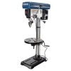
Wiring diagram for standard Micro-Mark 7x14 mini lathe. XMT-1135 control board.

Wiring diagram for mini mill with red and yellow emergency stop switch. FC350BJ/110V control board.

Wiring diagram for harbor freight mini lathe with illuminated rocker power switch and safety interlock circuit. FC250BJ/110V control board.

Wiring diagram for standard 7x12 (C2) mini lathe with red and yellow emergency stop switch. XMT-1125 control board.

Wiring diagram for standard 7x14 (C3) mini lathe. XMT-1135 control board.

Wiring diagram for Grizzly (X2) mini mill with 1/0 switch and red and yellow emergency stop switch. XMT-1135 control board.

Wiring diagram for mini mill with red and yellow emergency stop switch. XMT-1135 control board.

Wiring diagram for the Mini Mill Control Box Assembly. Works with any conventional mini mill (X2). XMT-1135 control board.

Wiring diagram for standard X3 and Grizzly G0463 mills. XMT-1160 control board.

Wiring diagram for a standard micro mill (X1). XMT-1115 control board.

Wiring diagram for the power feed for the X3 bench mill and HiTorque Mini Mills. XMT-1115J control board.

Additions or changes?

Back to Reference Information